|
S |
M |
T |
W |
T |
F |
S |
|
|
|
|
1
|
2
|
3
|
4
|
|
5
|
6
|
7
|
8
|
9
|
10
|
11
|
|
12
|
13
|
14
|
15
|
16
|
17
|
18
|
|
19
|
20
|
21
|
22
|
23
|
24
|
25
|
|
26
|
27
|
28
|
29
|
30
|
31
|
|
|
|
Forums10
Topics38,521
Posts545,765
Members14,419
| |
Most Online1,344
Apr 29th, 2024
|
|
|
|
Joined: Mar 2003
Posts: 122
Sidelock
|

Sidelock
Joined: Mar 2003
Posts: 122 |
Another try of my original sketch. I think this one is readable. 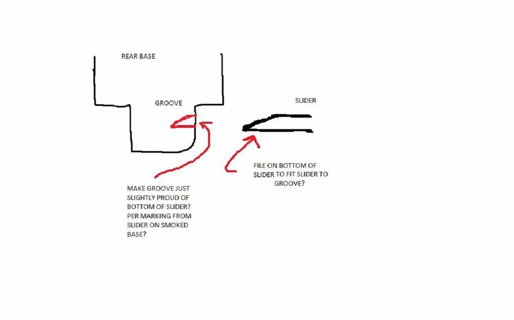
|
|
|
|
|
Joined: Mar 2003
Posts: 122
Sidelock
|
|
Sidelock
Joined: Mar 2003
Posts: 122 |
Is this a better sketch of how the location of the groove in the rear foot is determined? 
Last edited by rfankhauser; 09/12/13 01:07 AM.
|
|
|
|
|
Joined: Mar 2003
Posts: 122
Sidelock
|
|
Sidelock
Joined: Mar 2003
Posts: 122 |
And a sketch of my understanding of how the height of the rear claw mount ring is determined. Reading the text and sketching out a drawing sometimes helps me grasp the process better. 
|
|
|
|
|
Joined: Mar 2003
Posts: 122
Sidelock
|
|
Sidelock
Joined: Mar 2003
Posts: 122 |
Mike, I've reread your post several times and I believe I understand most of it. I really appreciate how much time you took to answer my questions. I still have a couple of questions though.
In your post you say the bases were skim milled to be parallel with the barrel flats. Just to make sure does this mean that the front base with dove tail installed is skim milled to be parallel with barrel flats? and the rear base is also installed and skim milled. Skim milling is only to make the top surfaces parallel to the barrel flats but does not necessarily make the front and rear bases the same level and I assume the wouldn't very often be at the same height?
A second question. When you determine the length of the feet or foot on the rear ring do you basically just use a depth gauge and insert the gauge in the slot until it hits the bottom of the base or the top of the barrels? Then the feet are contoured to the shape of the barrel and made to the length of the above measurement?
And last for now, I am still a little unclear how you would actually scribe the line on the rear foot to determine the location of the slot for the slider. I understand the concept but am unclear how you actually do this? Do you remove the slider and springs and somehow insert a scribe from the rear of the base? or do you remove the slider and springs and come in from the side of the base to scribe the line? Or could you just leave the slider installed and use the slider itself with some smoke and let the slider mark the line to be scribed? I'm just not quite getting how this is actually done.
Again, thanks for all your help. There just isn't much information out there on how this is done and while I don't mind learning through trial and error it can be frustrating. Sure helps to get some good information on how it is done.
Ron
|
|
|
|
|
Joined: Mar 2003
Posts: 122
Sidelock
|
|
Sidelock
Joined: Mar 2003
Posts: 122 |
Steve, Thanks for the tips and suggestions. I am pretty sure I'll have a scope mount completed before too long but whether or not it will return to zero when removed and installed will be the real test for me.
I'd really like to see a close up photo of your completed rings if you have a chance to post one.
Thanks,
Ron
|
|
|
|
|
Joined: Jul 2012
Posts: 4,468 Likes: 207
Sidelock
|
|
Sidelock
Joined: Jul 2012
Posts: 4,468 Likes: 207 |
Ron,
I believe your bases have already been "skim"milled to level them(when orig. installed).It would be very difficult to scrape them in level, and milling them level is easy(they have to be close though, or milling removes too much).The bases are not often the same height, just as you thought;this is where the boresighting/measuring distance to base comes in.The chord isn't used to tie the scope to the adjustable block,rather it is to fasten the scope to the rifle, with the block trapped between( you need to be able to remove the block to adjust it).
The depth gage at the end of the caliper(or any other type)is used to measure from the top of the base to the top of the barrels,through the opening for the foot.Measure to the lowest spot,mill the foot to this length, then contour it to approximately fit the barrels.The foot should't bear on the barrels, though, or it may interfere with other fitting.
Once the foot is fitup(the slider and springs should have been removed for this operation),you can reach in through the slots on the side and scribe a line on each side with a sharp scriber.If you don't have one, it can be easily made.
If you can find a gun with clawmounts that have been mounted in Germany, or by a Germany trained gunsmith, inspecting it closely can help you a lot, to see how deep to make the slot in the foot for the slider,the angles, etc.The trouble with learning through trial and error is that the cost of the error can be pretty high, if you have to buy new parts.Let us know how it works out, and as always, I'll do what I can to help.
Mike
|
|
|
|
|
Joined: Apr 2013
Posts: 688 Likes: 48
Sidelock
|
|
Sidelock
Joined: Apr 2013
Posts: 688 Likes: 48 |
When I made mine I just set two quarter inch screw driver bits on my bases and taped(electricians tape so it would stretch) the scope to the barrels. I made sure the scope was optically centered and used a laser bore sighter and shimmed the rear of the scope to determine the difference in height between the front and rear base.
Interestingly my bevel on the slider is just the opposite, wedging the rear base tighter as it moves forward. My rear legs are shorter than the depth of the base, which makes sense to me as a slightest bit dirt in the base would not allow it to return to zero.
Last edited by oskar; 09/12/13 12:56 PM.
After the first shot the rest are just noise.
|
|
|
|
|
Joined: Jul 2012
Posts: 4,468 Likes: 207
Sidelock
|
|
Sidelock
Joined: Jul 2012
Posts: 4,468 Likes: 207 |
oskar,
The slider should be parallel where it locks into the foot, the slight bevel on top is to help cam the slider back, when installing the scope(the corner on the bottom should also be "broken" a little to get it started).The reason for fitting the slider to the feet(with the notch being a little proud)is to take all "play" out.As far as the lazer boresighter is concerned, I have no experience with them, If it works, use it. When working on a drilling or BBF, a conventional bore sighter can't be used w/o some kind of adapter.I'm not putting down your work at all, I admire anyone with the guts and ability to mount one. I'm just reporting what I learned at the hands of a master,some of which I know seems counterintuitive.
Mike
|
|
|
|
|
Joined: Mar 2003
Posts: 122
Sidelock
|
|
Sidelock
Joined: Mar 2003
Posts: 122 |
Ron,
I believe your bases have already been "skim"milled to level them(when orig. installed).It would be very difficult to scrape them in level, and milling them level is easy(they have to be close though, or milling removes too much).The bases are not often the same height, just as you thought;this is where the boresighting/measuring distance to base comes in.The chord isn't used to tie the scope to the adjustable block,rather it is to fasten the scope to the rifle, with the block trapped between( you need to be able to remove the block to adjust it).
The depth gage at the end of the caliper(or any other type)is used to measure from the top of the base to the top of the barrels,through the opening for the foot.Measure to the lowest spot,mill the foot to this length, then contour it to approximately fit the barrels.The foot should't bear on the barrels, though, or it may interfere with other fitting.
Once the foot is fitup(the slider and springs should have been removed for this operation),you can reach in through the slots on the side and scribe a line on each side with a sharp scriber.If you don't have one, it can be easily made.
If you can find a gun with clawmounts that have been mounted in Germany, or by a Germany trained gunsmith, inspecting it closely can help you a lot, to see how deep to make the slot in the foot for the slider,the angles, etc.The trouble with learning through trial and error is that the cost of the error can be pretty high, if you have to buy new parts.Let us know how it works out, and as always, I'll do what I can to help.
Mike Mike, I believe most of what you said in your last messages makes sense to me. But I just want to clarify a couple of points to make sure. When the bases are skim milled is the front base skim milled with or without the dove tail plate installed? Or is just the dove tail plate (base) that is skim milled? In my case this was already done when orig installed but just trying to make sure in case I do another set sometime? Just not quite clear on the skim milling and trying to understand it. The clarification on the chord makes sense. It is simply used to temporarily attach the scope (in the rear portion) to the barrels so the gun can be boresighted by actually firing the gun at 100 yrds. I may be wrong but I assume this is to get the scope close to correct so that the scope has enough room to adjust it internally using the elevation and windage dials. The scope and gun need to be boresighted (and installed close to correct) to ensure that you do not run out of internal adjustment on the scope dials. On my install I thought about this but pretty much just used a long straight edge to make sure the scope was installed relatively level with the barrels and looked appropriate. I also did some testing using a bore sighter (not laser) and it looked like I was going to have the scope close enough that I could complete the scope adjustment using the scope dials and not run out of movement room. Also, I felt it was important to have the feet on the front ring installed fairly parallel to the front base if that makes sense. In other words I wanted the front feet to sit parallel to the front base and this limited how much I could raise or lower the scope in the back. I could see how you could make minor adjustments though. A very helpful tip on the feet and what they should bear on. I have been trying to make the rear foot bear on the barrels as well as the bottom of the ring and I even thought that possibly the foot bearing on the barrels was the most important bearing. So, I will now shoot for having the feet close to the barrels but have the rear scope ring bear on the rear scope base. In other words the flat area that surrounds the foot will bear on the rear base. I assume that having this done well helps to ensure that the scope returns to zero each time it is removed. And as Oskar noted if the foot is bearing on the barrels all it would take is a little dirt to get in the slot and then this might affect the return to zero. I'd like to examine a completed set of claw mount scope rings that were done correctly and I can see how that would help. At this point I have only been able to examine photos I have found on the internet of claw rings and bases. I'll keep looking for better examples though. And yes, trial and error can get expensive. I have ruined at least (2) sets of front and rear bases but have been able to use my TIG welder to add metal in the appropriate places and put them back in service (and start over). Again thanks to everyone for this very helpful thread. Makes the learning process easier and when I get a set of rings "good enough" I'll post a photo. Might be awhile yet though! Ron
|
|
|
|
|
Joined: May 2011
Posts: 742
Sidelock
|
|
Sidelock
Joined: May 2011
Posts: 742 |
Ron, you are correct about having the flat area that surrounds the foot down onto the rear base--that is very important. The feet touching the barrels on the bottom is unwanted, BUT get it as close as possible, including contouring, so that it is as strong as possible in resisting upward prying forces during recoil, which is where I have seen one fail.
Concerning the fitting of the slide, here is my concern: human perfection not being a possibility, design it so that, as Mike said, it pushes down on the foot. How? Well, since there are tolerances involved in the fit of the slide to the horizontal slot it moves in, something has to "take up the slack" of those tolerances, or it isn't really tight. I decided it should be the slot that forms the top of the feet. I angled it EVER so slightly "uphill". As it is polished, it gets really tight just as the slide is coming to the end of its travel. In fact you have to give it a push to complete the travel. A wear mark on the side of the rear base conveniently showed when the slide had maxed out. It may be that Mike's plan is better on several accounts and less risky. But if I were to adjust the slide instead of the slot for the feet, I would STILL adjust it at a slight, slight angle in order to tighten up. A perfectly level slot is probably not a possibility. Even if it were, the area that sits down on the top of the base probably wouldn't be perfectly leveled, and that would tilt things. The slide is microscopically loose in its groove. And even if everything were perfect, by the time you got the slide to move over the perfectly level foot, it would not be pushing down with much force AND WOULD NOT GET TIGHTER, since it would slide across at a straight angle. I want it to unmistakably get tight! 25-30% of the claw mounts I have inspected on guns were a bit loose if you took the time to lift up on the rear of the scope--they moved! And of course to varying degrees. The first I saw was on a spankin' new Mannlicher Schonauer back in the late sixties. The person who had shelled out a wad of bills for those days was so upset he returned it to the vendor. So if you are going to err, err on the side of things getting progressively tighter. We are not talking about the kind of angles that will lock up after recoil, especially if nicely polished to fit. Steve PS...I don't know how to do pictures yet.
|
|
|
|
|
