|
S |
M |
T |
W |
T |
F |
S |
|
|
|
|
1
|
2
|
3
|
4
|
|
5
|
6
|
7
|
8
|
9
|
10
|
11
|
|
12
|
13
|
14
|
15
|
16
|
17
|
18
|
|
19
|
20
|
21
|
22
|
23
|
24
|
25
|
|
26
|
27
|
28
|
29
|
30
|
31
|
|
|
|
Forums10
Topics40,204
Posts572,078
Members14,682
| |
Most Online32,084
Jun 14th, 2026
|
|
|
|
Joined: Feb 2004
Posts: 13,883 Likes: 21
Sidelock
|

Sidelock
Joined: Feb 2004
Posts: 13,883 Likes: 21 |
Interesting hunter arms drawing. No rim rad, just a chamfer. Yeah, I wonder if that drawing is for a barrel tube before assembly to a barrel set?
|
|
|
|
|
Joined: Dec 2001
Posts: 12,743
Sidelock
|
|
Sidelock
Joined: Dec 2001
Posts: 12,743 |
It doesn't really show in the drawing but if you do the math you will find the rim set has a 25� face & ends in a short parallel diameter behind the face. On the 12 gauge rim seat for instance you will have about a .025 deep section @ .885" diameter & then the 25� ace which goes to a total depth of .065". According to "Plans & Specifications" drawings by 1935 the 16 gauge bore had been increased to .662" diameter & the 20 gauge shell had been lengthened to 2 3/4". 16 gauge remained @ 2 9/16". .410 chambers had been added in both 2�" & 3".
That 1 7/8" in 12�" taper of the cone in the 1907 drawing figures to an angel of 4�17'21". By the 1935 drawings the cones had been lengthened with an angle of;
12 gauge = 3�1'; 16 & 20 gauges = 3� 13' & .410 = 2�26'
in the 12, 16 & 20 gauges this would give cone lengths of approximately 5/8". In the .410 even though the angle is shallower there is less difference in chamber & bore diameters so the cone would fall a bit short of 5/8" (.625") @ about .600". By today's standards these are still considered short cones but over the years have functioned well with a wide variety of shells beginning with those wadded with card & felt & on into the plastic era. I see little reason to change one of them.
Miller/TN
I Didn't Say Everything I Said, Yogi Berra
|
|
|
|
|
Joined: Jan 2002
Posts: 11,575 Likes: 182
Sidelock
|
|
Sidelock
Joined: Jan 2002
Posts: 11,575 Likes: 182 |
C.I.P. didn't ask my opinion Bill, but I don't think Federal Premium Wing-Shok High Velocity 20g loads are available in the EU  As you observed, C.I.P. 20g service and proof pressures are higher than 12 http://www.cip-bobp.org/homologation/en/tdcc_public?page=1&cartridge_type_id=712g 65mm and 70mm �standard proof� lead or steel (limited to no larger than 3.25 mm and max. fps 1,300) transducer psi SERVICE pressure 740 BAR = 10,733 psi; PROOF 930 BAR = 13,489 psi Both 65 and 70 mm 16g standard is SERVICE 780 BAR or 11,313 psi; PROOF 900 BAR or 13,053 psi. Both 65 and 70 mm 20g standard is SERVICE 830 BAR or 12,038 psi; PROOF 1040 BAR or 15,084 psi. And the Hunter Arms "Close Enough for Farm Implements" illustration   Drew, interesting to note re CIP service and proof pressures: Although the 16 has a higher service pressure than the 12, it has a lower proof pressure. Seems counter-intuitive.
|
|
|
|
|
Joined: Jan 2006
Posts: 9,999 Likes: 602
Sidelock
|
|
Sidelock
Joined: Jan 2006
Posts: 9,999 Likes: 602 |
Thank you Larry; it's a typo and should be 980 = 14,214 psi. I'll correct the original post, and a bunch of other places 
|
|
|
|
|
Joined: Feb 2004
Posts: 13,883 Likes: 21
Sidelock
|
|
Sidelock
Joined: Feb 2004
Posts: 13,883 Likes: 21 |
It doesn't really show in the drawing but if you do the math you will find the rim set has a 25� face & ends in a short parallel diameter behind the face. On the 12 gauge rim seat for instance you will have about a .025 deep section @ .885" diameter & then the 25� ace which goes to a total depth of .065". According to "Plans & Specifications" drawings by 1935 the 16 gauge bore had been increased to .662" diameter & the 20 gauge shell had been lengthened to 2 3/4". 16 gauge remained @ 2 9/16". .410 chambers had been added in both 2�" & 3".
That 1 7/8" in 12�" taper of the cone in the 1907 drawing figures to an angel of 4�17'21". By the 1935 drawings the cones had been lengthened with an angle of;
12 gauge = 3�1'; 16 & 20 gauges = 3� 13' & .410 = 2�26'
in the 12, 16 & 20 gauges this would give cone lengths of approximately 5/8". In the .410 even though the angle is shallower there is less difference in chamber & bore diameters so the cone would fall a bit short of 5/8" (.625") @ about .600". By today's standards these are still considered short cones but over the years have functioned well with a wide variety of shells beginning with those wadded with card & felt & on into the plastic era. I see little reason to change one of them. You may want to double check your trig. This is a modern chamber/cone drawing. It typifies the modern cone considered to be longer than many early 20th century guns. As you can see, it has a 5* angle per side or 10* included angle cone. A 3* cone measured from either the barrel axis or normal to the barrel axis doesn't jive. 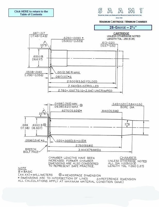
|
|
|
|
|
Joined: Dec 2001
Posts: 12,743
Sidelock
|
|
Sidelock
Joined: Dec 2001
Posts: 12,743 |
Chuck;
Those angles were taken directly from the L C Smith drawings.
Note that SAAMI drawing is for a "Minimum Chamber". I believe they are saying that is the steepest angle (Shortest cone) they recommend, not that it should not be exceeded in length.
Based up on actual chamber & bore dimensions the small (Forward) end of most chambers are approximately .070" larger than nominal bore or .035 per side. 1/X Tan 5� x .035 = .400" for the length of this cone.
The trig is good, the fallacy is in assuming that 5� represents a modern long cone. A 1�" long cone with .035 difference per side between chamber & bore would be an angle of 1� 20' 12".
Miller/TN
I Didn't Say Everything I Said, Yogi Berra
|
|
|
|
|
Joined: Feb 2004
Posts: 13,883 Likes: 21
Sidelock
|
|
Sidelock
Joined: Feb 2004
Posts: 13,883 Likes: 21 |
Miller,
I have several gauges of SAAMI spec reamers from two makers. All are 5* cones. The reason I know is I had to have one reamer re sharpened due to damage on the cone area. I checked it on an O.C.. The 5* dimension is specified as a "basic" dimension, which means it is specified without tolerance.
My only references on forcing cones in LC Smiths are a few that I have owned and the two I have now. I haven't measured them.
Last edited by Chuck H; 11/06/15 09:11 PM.
|
|
|
|
|
Joined: Dec 2001
Posts: 12,743
Sidelock
|
|
Sidelock
Joined: Dec 2001
Posts: 12,743 |
Chuck;
All I can tell you is "Do The Math". Any chamber cut with a cone angle of 5� per side is going to be a short one. It will not be a "Modern Long Cone", period. In my 35+ years in the machine shop I have cut enough angles & tapers to know how to calculate them.
I Double & Triple checked my trig, it is correct.
If you take the 1907 drawing Drew posted with the included taper of 1 7/8" per 12�". Do the trig on this taper & you get 4� 17' & 21 angle" per side. Calculating the length of cone for the .069" difference in chamber & bore diameters gives a length of .460".
Double checking by another means that .069" is 3.68% of 1.875.
3.68% times 12.5 = .460"
With that same .069" difference between chamber & bore a 5� angle per side would give a cone length of .394", certainly not a long cone.
Remember SAAMI is suggested Not Law.
Miller/TN
I Didn't Say Everything I Said, Yogi Berra
|
|
|
|
|
Joined: Jan 2006
Posts: 9,999 Likes: 602
Sidelock
|
|
Sidelock
Joined: Jan 2006
Posts: 9,999 Likes: 602 |
Cerrosafe chamber and forcing cone casting courtesy of Marcus Merritt 
|
|
|
|
|
Joined: Jan 2002
Posts: 5,954 Likes: 15
Sidelock
|
|
Sidelock
Joined: Jan 2002
Posts: 5,954 Likes: 15 |
Late to the party, but am passing along the following reminder. Shot passage/flow through the forcing cone constriction, as with the choke constriction, is an orderly process, not some slam, bam chaos. The leading shot pellets speed up to get out of the way of the following pellets. Since there is no extra energy input available, the velocity increase must come at the expense of pressure. That is, the pressure drops across the forcing cone constriction and across the choke constriction. I know this is counter-intuitive, but it is so. If not, airplanes don't fly.
Post back if you desire further discussion.
DDA
|
|
|
|
|

